
Voltage drop, not ampacity, usually limits how far you can run 10/2 cable on a 20 amp breaker; with a full 20 A continuous load the practical one-way maximum is about 90 feet when using a 3 percent voltage-drop limit on a 120 V branch circuit. This conclusion matters because 10 AWG copper is permitted by the NEC on a 20 A breaker from an ampacity perspective, but its DC resistance produces measurable drop over long runs that can cause motors and electronics to underperform.
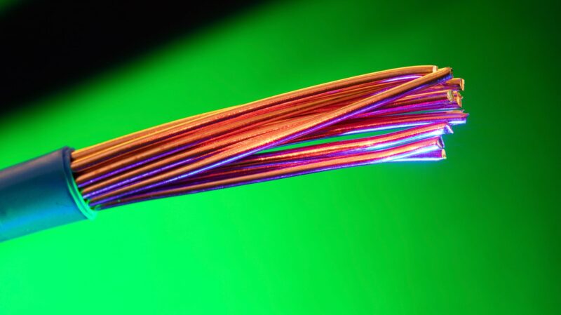
Practical One-Way Distance Benchmarks
Using a 3 percent target on a 120 V circuit, a continuous 20 A load reaches about 90 feet one-way. That result assumes a simple round-trip voltage-drop model and a practical 10 AWG copper resistance near 1.0 ohm per 1,000 feet. Allowing a 5 percent drop pushes the one-way distance to roughly 125-130 feet, and halving the current approximately doubles the allowable distance.
Quick Voltage Drop Calculation Steps
To check any run quickly:
- Establish conductor DC resistance. Use 1.0 ohm per 1,000 feet for 10 AWG copper as a practical design value; for precise work see the American Wire Gauge (AWG) table and resistance information.
- Compute round-trip resistance for one-way length L: R_rt = 2 × R_per_1000ft × (L / 1000).
- Calculate voltage drop: VD = I × R_rt, where I is the expected load current.
- Convert VD to a percentage of source voltage and compare to your target percent (commonly 3 percent for branch circuits).
Reference Distances for Typical Loads
| Typical Load | One-Way Distance (3% VD) | Practical Note |
|---|---|---|
| 20 A continuous | ≈ 90 ft | Design default for a full 20 A draw on 120 V |
| 10 A typical | ≈ 180 ft | Half the current roughly doubles the allowable distance |
| 5% drop allowance | ≈ 125-130 ft at 20 A | Use cautiously; acceptable for non-sensitive loads or combined feeder/branch accounting |
Why Ampacity Compliance Is Not the Whole Story
The NEC allows using larger conductors on smaller breakers, so 10/2 on a 20 A breaker meets ampacity rules. The remaining concern is service performance: voltage drop can reduce motor starting torque, dim lighting, or cause electronic power supplies to operate outside their regulation range. For equipment with tight voltage tolerances, design to a stricter percent drop or upsized conductors.
How Installation Type Changes Real-World Performance
Conductor resistance is intrinsic, but installation conditions alter thermal behavior and derating. NM-B cable, UF-B, MC, and bundled THHN in conduit all use 10 AWG copper, yet grouping, conduit fill, and elevated ambient temperatures increase operating temperature and lower allowable current. When runs are long and heat buildup is possible, evaluate conductor ampacity derating together with voltage-drop calculations.
When Upsizing or Alternative Strategies Make Sense
Choose one of these solutions when a calculated run exceeds your target distance:
- Upgrade to 8 AWG conductors to reduce voltage drop without changing supply topology.
- Locate a small subpanel nearer to concentrated loads and run a correctly sized feeder to minimize long branch runs; see the site guide on wiring a common 240 V load for related feeder considerations at what size wire for electric water heater.
- Split heavy loads across separate circuits to lower current per conductor and shorten individual run lengths; for general 220 V circuit sizing guidance consult the 220 V gauge guide.
On-Site Verification Procedures
Field measurements are decisive. Measure voltage at the far device under the expected loaded condition; compare that reading to the supply voltage and your target percent drop. Confirm conductor type and labeling at both ends. Check termination torque and look for corrosion or loose lugs, because poor connections can add several ohms or more in contact resistance and mimic the effect of a much longer run.
Common Design and Installation Mistakes
Frequent errors that shorten the effective run include underestimating motor inrush, bundling conductors without applying NEC derating factors, ignoring elevated ambient temperatures, and treating calculator outputs as final without on-site verification. When in doubt, size conservatively or provide a subpanel to avoid marginal voltage at critical equipment.
Additional Practical Resources
Manufacturer voltage-drop tables and online calculators speed planning and double-check manual calculations; product pages often list conservative resistance values and example runs. For related wiring-type differences and field practice, see the site primer comparing common cable types at the 14-2 versus 14-3 wire guide. For larger 240 V appliance runs that face similar drop issues, the water-heater guide linked above summarizes when to upsize conductors versus change breaker sizing.
Summary Recommendation
Design 10/2 branch runs to keep voltage drop at or below 3 percent under expected continuous load; use the 90-foot benchmark for a 20 A continuous load as a practical starting point. When loads approach the limit, verify with on-site loaded measurements and choose upsizing to 8 AWG or a nearer subpanel rather than relying on ampacity alone.
Related Video
Understanding how far you can run 10/2 wire on a 20 amp breaker is crucial for safe electrical installations. Factors such as voltage drop and the specific use case will influence the maximum distance. Generally, for most applications, a run of up to 100 feet is acceptable, but doing the math for your specific situation can ensure compliance with electrical codes and safety standards.
More from Architecture Adrenaline
For additional insights and information related to electrical installations and more, you can follow our social channels. Find more posts like this one on our Instagram page.